I have some experience in Mach3 CNC software in past. I love this software and the simple setup of Mach3 liked CNC controller software. Actually, it combines half of CNC and stepper controller functions in PC software. Even and old PC can be the best choice for this option. But there is one drawback or limitation in this, LPT port. Most of these software use LPT port for interfacing with stepper and CNC. Most modern PC no longer used LPT. Actually, I have some old laptop and PC with LPT builtin. But I like to search the net for better option.
Yes, there must be two important things for me, must be free, opensource and simple.
After reading many DIY CNC build logs, I choose Grbl controller with DIY arduino board. For stepper, I already built Linistepper controllers.

From Grbl Wiki,
“Grbl is a free, open source, high performance software for controlling the motion of machines that move, that make things, or that make things move, and will run on a straight Arduino. If the maker movement was an industry, Grbl would be the industry standard.”
Thanks Grbl buys for developing such simple/effective controller.
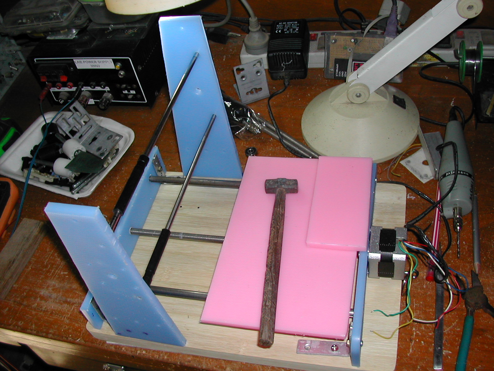
It is time to assemble main controller after finishing DIY Arduino and stepper controller boards a few weeks ago. There are some tasks.
- Flashing Arduino with grbl firmware
- Configuring Grbl for my CNC machine
- Connecting Grbl with stepper controllers and CNC
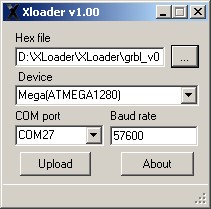
1# The first test is to flash DIY Arduino board with “Grbl”. It is straight forward. Wiki is your help. Another helpful source is “Shapeoko”, fully opensource and commercial CNC wiki.
https://github.com/grbl/grbl/wiki/
https://github.com/grbl/grbl/wiki/Flashing-Grbl-to-an-Arduino
http://www.shapeoko.com/wiki/index.php/Grbl
I used Xloader and flashing done after minutes. I used V0.9i version.
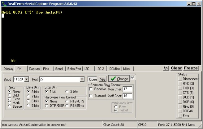
After flashing the Grbl firmware, I connected with 115200 baud rate and hit enter key. I saw Grbl version and some message. Grbl is alive.
2# Configuring Grbl
I used last updated Grbl 0.9i version. This version is a bit different from old versions. Most of 0.9 user face difficulties in using this. And version 9.0x also has some issues with PC side software in some case. But, I choose this version 0.9i for testing some advanced features.
- Default serial baudrate is now 115200! (Up from 9600)
- Full Limit and Control Pin Configurability
- Soft Limits
- Probins
- Compile-able via Arduino IDE!
2.1# Type “$” for help and “$$” for default configuration.
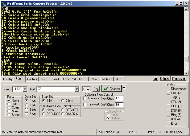
Here is grbl default config. Before starting, check a look grbl wiki for how thing are sorted.
$0=10 (step pulse, usec)
$1=25 (step idle delay, msec)
$2=0 (step port invert mask:00000000)
$3=6 (dir port invert mask:00000110)
$4=0 (step enable invert, bool)
$5=0 (limit pins invert, bool)
$6=0 (probe pin invert, bool)
$10=3 (status report mask:00000011)
$11=0.020 (junction deviation, mm)
$12=0.002 (arc tolerance, mm)
$13=0 (report inches, bool)
$20=0 (soft limits, bool)
$21=0 (hard limits, bool)
$22=0 (homing cycle, bool)
$23=1 (homing dir invert mask:00000001)
$24=50.000 (homing feed, mm/min)
$25=635.000 (homing seek, mm/min)
$26=250 (homing debounce, msec)
$27=1.000 (homing pull-off, mm)
$100=314.961 (x, step/mm)
$101=314.961 (y, step/mm)
$102=314.961 (z, step/mm)
$110=635.000 (x max rate, mm/min)
$111=635.000 (y max rate, mm/min)
$112=635.000 (z max rate, mm/min)
$120=50.000 (x accel, mm/sec^2)
$121=50.000 (y accel, mm/sec^2)
$122=50.000 (z accel, mm/sec^2)
$130=225.000 (x max travel, mm)
$131=125.000 (y max travel, mm)
$132=170.000 (z max travel, mm)
# Important, you need to noted these before configuring grbl.
- Your stepper controller, step pulse duration. If not sure, use default value, 10 us and trial and error method. (My Linistepper min step pulse is 3 us, so 10 us is fine for me)
- X,Y,Z stepper motors step/revolution (eg: 200 steps/rev for my stepper specs)
- Microstepping, half step or full step configuration for stepper motor controller ( I choose 6th microstep for my linisteppers )
- X,Y, Z Lead screw’s pitch, turn/mm
- X,Y,Z axis maximum travel distance Not your bed or axis dimension, how much your axis actually moved. (Mine is X=160 mm , Y = 160 mm and Z = 55 mm)
- Have you use limit switches for homing and max limits of each axis? Some very small CNC machine may not use limit switches but strongly recommended to use in most case. It will convenience and protect crashing your machine. I used 2 x limit switches for each axis, total six, used for both max limit and homing.
# Some parameters should be configured after you connect grbl with steppers controllers and CNC. For example, axis direction should be configure after the first test run. After you test move one axis, if you check and want to reverse, simple configure this option at that time. I also noted these configs as post configurations.
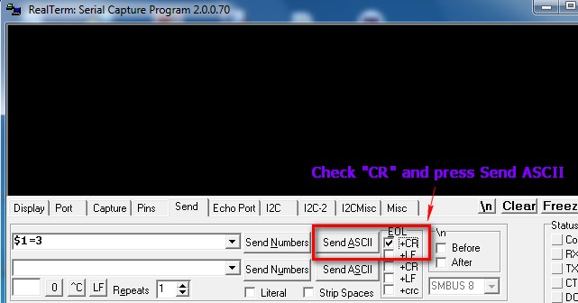
2.2# OK, configuring parameters is simple. You can use any serial Terminal software like putty. I use RealTerm, my fav serial Terminal software. Type the parameter and value exactly, press Enter and grbl will save the new value in EEPROM instantly.
For example, to configure new step pulse value 3 us, just type in and press Enter this.
$1=3
Sample screen shoot from RealTerm.
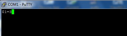
Just sample screen shoot for putty. Type in at the terminal window.
2.3# Axis Direction ($3)
#(This should be a post configuration after finishing connection with CNC hardware)
There are many explanations in many forums. I want is simple. Just drive test my X, Y, Z motor after finish all config. I checked my Z axis direction is wrong Up and Down. I just set the Z-axis dir invert bit as “1”. You need to set only 3 bits, LSB is for X axis. Second LSB bit is for Y. Third LSB bit for Z. In my case, I want to invert Z direction only and mask in binary is “00000100” and “4” in decimal. So, the config is like this.
$3=4
2.4# Homing Config
Arr, homing in grbl is a bit confusing thing. I notice many people troubled in this.
OK, first thing first. I used limit switches and homing. So, pre-configure these two first.
$21=1
$22=1
#This is also a post config. Then check your homing direction by entering “$H” command after you finished connection with CNC machine. Like axis dir inverse mask, if your homing direction of XYZ axis is wrong, just SET inverse mask bit. That all. I checked later that my X,Y axis homing directions are wrong. So, I set the bits for XY and my mask is “00000011” and in decimal, it is “3”.
$23=3
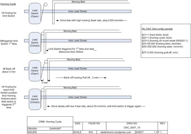
# Again, it should be also post config. Homing feed rate and seek rate. It is the most confusing part in Grbl. Grbl homing cycle always take two steps, seeking and feeding. First, it drives the axis with faster seek rate (in default $25=635.000 (homing seek, mm/min, mine is 250 mm/min). So, the axis drive to limit switch very fast in first seek cycle. Be aware, if seeking rate is too him your stepper will not move and stalled, start with 250 and increase until the highest speed. When the axis hit limit switch, it back-off a few mm until release the switch (in default 1 mm, $27=1.000 (homing pull-off, mm), mine is 3 mm). After the switch is released, the axis drive forward again with slower rate to determine the exact position of limit switch trigger ($24=50.000 (homing feed, mm/min), in most case, default is fine). After limit switch is triggered again, homing for this axis is finished.
Here is my homing seek,feed and pull-off configs. Also see the fig for homing cycle.
$24=25.000
$25=250.000
...
$27=3.000
2.5# 2.5# Axis Step per Milimeter
This is configured how many steps needs for axis driver to drive 1 mm distance. There is a formula in grbl wiki.
steps_per_mm = (steps_per_revolution*microsteps)/mm_per_rev
Here is my driver config,
Step/Rev =200
Microstep = 6
mm/rev = 1.2876
Then, Step/mm = (200×6)/1.2876 = 931.966 ( 3 digits and 3 decimal place format)
Then, configured for grbl
$100=931.966
$101=931.966
$102=931.966
2.6# Last, Max travel distance for ZYZ Axis
Just need to configure the max movable distance for all axis. Need to measure your axis movement carefully. My config is as follows.
$130=160.000
$131=160.000
$132=55.000
Finally, here is my Grbl config. I used limit switches and homing. The rest are left in default.
$0=10 (step pulse, usec)
...
$3=4 (dir port invert mask:00000100)
...
...
$21=1 (hard limits, bool)
$22=1 (homing cycle, bool)
$23=3 (homing dir invert mask:00000011)
$24=25.000 (homing feed, mm/min)
$25=250.000 (homing seek, mm/min)
...
$27=3.000 (homing pull-off, mm)
$100=931.966 (x, step/mm)
$101=931.966 (y, step/mm)
$102=931.966 (z, step/mm)
$110=300.000 (x max rate, mm/min)
$111=300.000 (y max rate, mm/min)
$112=300.000 (z max rate, mm/min)
...
$130=160.000 (x max travel, mm)
$131=160.000 (y max travel, mm)
$132=55.000 (z max travel, mm)
Next part is assembling and connecting all together.
Oakkar7
okelectronic.wordpress.com