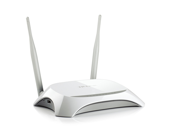
TP-Link TL-MR3420 V3 LEDE(OpenWRT fork) Custom Build

# This is just my old build log for TP-Link TL-MR3420 V3 LEDE (OpenWRT fork) custom build firmware.

Forums thread is here >> https://forum.lede-project.org/t/tp-link-tl-mr-3420-v3-build/855

I have some experience in openWRT platform and it’s hack-able features. I like and select to buy this 3420 router because this one is dead cheap and full featured, especially support with USB and 3G modem. Some alternative like 3020 and 703 are also cheap but very small and no feature like eth-switch and little gpio. But problem is TL-MR 3420 V3 is not supported by openWRT. So, I have to build my own custom firmware. I choose LEDE (the fork of openWRT) build.

1- First build attempt

I recently build TL-MR 3420 V3 firmware which was not yet supported by openwrt.
The board is very similar to V2 board but V3 is with new processor Qualcomm Atheros QCA9531.

My V3 Board specifics brief are as follows:
– Qualcomm Atheros QCA9531 650MHz
– 25Q32CS1G 4M
– Zentel A3S56D40FTP -G5 32 MiB

I started with TL-MR 3420 V2 profile.
“Target System” ⇒ “Atheros AR7xxx/AR9xxx”
“Target Profile” ⇒ “TP-LINK TL-MR3420 v2”

Build success without showing any error.
Then I tried to build from stock web based firmware upgrade but failed with error 18005 because of TP-Link genuine firmware check hash.
So, I tried with serial/tftp flash method and flashing “lede-ar71xx-generic-tl-mr3420-v2-squashfs-factory.bin” was successful :slight_smile: . LEDE is booted checked from serial console.

Error : But when I check from serial console, ifconfig shows only lo interface. No Eth/Wan nor WLAN is up.

Tried ./etc/init.d/network reload and show error.

root@lede:/# /etc/init.d/network reload
Failed to connect to the switch. Use the "list" command to see which switches are available.
[   56.975151] IPv6: ADDRCONF(NETDEV_UP): br-lan: link is not ready
'radio0' is disabled

Checked boot log and noticed errors.

[    0.115999] ar71xx: invalid MDIO id 1
[    1.414894] ag71xx ag71xx.0: invalid speed specified
[    1.420074] ag71xx: probe of ag71xx.0 failed with error -22
[    2.014883] ag71xx ag71xx.1: invalid speed specified
[    2.020033] ag71xx: probe of ag71xx.1 failed with error -22

Seem Switch/Eth driver is failed to load. How can I add network support for my board. If someone has experience on this series, also let me know.

Forum user @ahmadrasyidsalims point me out for the patch >>

I think you should be try :joy:

———————————————————————————————-

2- Second attempt

After loosing some hairs, some coffees + some nights, it was successfully booted and worked 🙂 .
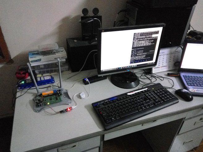
TP-Link TL-MR-3420 V3 LEDE ( OpenWRT ) Custom Build

I re-patch this manually in current lede build.
In “menuconfig”, there is an option for “TL-MR3420 V3” profile. Good!!

This patch works basically,
– “lede-ar71xx-generic-tl-mr3420-v3-squashfs-factory.bin” was flashed and booted without any error
– LAN & WAN configured and works well now
– status LED works but other LED not
– USB storage is detected but 3G dongle not tested

Issues:

  •  like other 4Mib flash router, space left in overlay/roots_data lefts only 492k
  • no space to install luci nor USB support package
  • – Seem extroot is solution but I want to use 3G dongle for usb.

Anyway, I have to rebuild firmware with removing some packages.
And any suggestion for which packages should be removed??

And some suggestion thankfully accepted 🙂 .

If you want to strip either PPPoE or IPv6, make sure you deselect the top LuCI entry as well, so you can deselect LuCI’s PPPoE support (and I think the same applies to IPv6).

you should be able to fit packages if you select them with “y” so they are integrated on build time. Build time integration compresses packages, 500k should be enough for luci and usb if integrated like that.

seem extroot is solution but I want to use 3G dongle for usb. >>

There are 3G/4G dongles with a microSD slot, you can do extroot there and be happy.
For example Huawei E3372h.
You can keep 3g/4g dongle tools in the extroot, as even if it does not detect the dongle’s modem it will detect the usb storage on it fine, so it will extroot and then detect the modem too.

———————————————————————————————-

3 – Third Attempt (Success)

Finally, tried to manage packages to fit in 4MiB. After removing some packages, custom build firmware worked fine with V-3 hardware.

For those who want to try, I build two versions. One for standalone and another for extroot support. Both versions removed ipv6 and pppoe supports.

1) This version supports
* Luci+bootstrap,
* 3G, usb, and
* ext-4 file system. Like @bobafetthotmail said, this version can detect SD card inside 3G-dongle.
* And I added mwan+luci-app-mwan3 for multi-wan support. Tested this also worked (Failed-over worked, load balancing is not tested)
Leaving about 104k space after flashed. Good point is you can still use extroot with this build (with ext-4, no vfat)

LEDE_TL-MR3420-V3_Luci_Bootstrap_3G_USB_Ext4_MWAN70

2) This version-2 is especially for extroot
* Luci+bootstrap,
* usb, and ext-4 and VFAT file system. This version can also detect SD card inside 3G-dongle.
* No mwan3 and no serial, no 3G dongle support. You can install whatever after extroot :slight_smile:
Leaving about 76k space after flashed.

LEDE_TL-MR3420-V3_Luci_Bootstrap_USB_Ext4_VFAT30

By the way, Dear LEDE admin and developers, LEDE aimed for flash at least 8MiB, right!. But the problem is these cheap routers with USB support only have mostly 4MiB. Pls also consider for devices with 4M flash for some transition time.

thanks all,
oakkar7

DIY csCNC – 8 (PC softwares)

This is Just a follow  up post of my csCNC ver 1.0.  to warm up my hand after a long idle time in this blog.

After building hardware, I searched for available software options for running G-code, CAM jobs in PC. Options are the same as hardware. It must be free or opensource and also not a complex one. In short, I selected the following options.

SketchUp (Formerly from Google) 2D and 3D drawing software for drawing/cutting wood, plastic materials

Inkscape (open source vector drawing tool) for drawing vector image of bitmap image to vector converting

Eagle (Schematic and PCB designer, limitted but value worth free version available) my fav schematic and PCB tool

HeeksCNC (CAD/CAM software, opensource, but not free, for only £10, a bit confused 🙂 , source code is opensource and final application is not free. There is also trial version here. ) for converting drawing to G-code

OpenSCAM (opensource CAM simulation tool) for viewing and simulation g-code

Grbl Controller 3.0 (Gcode sender for Grbl) to send GCode to CNC machines

There are some important issue tips on using Grbl v0.9i with Grbl Controller 3.0.

  • At the first run, try to move Z first with axis control buttons. It will set feed rate first. If you jogs X,Y axis first, grbl will show “error:Undefined feed rate” error message. Grbl wiki said “Older Grbl versions had a default feed rate setting, which was illegal and was removed in Grbl v0.9.”.
  • Try soft-reset “$X” and try “$H” for homing. Home button from GUI is will not work after the first homing cycle is finished.


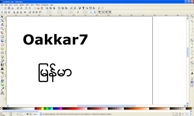
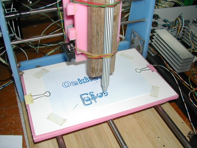
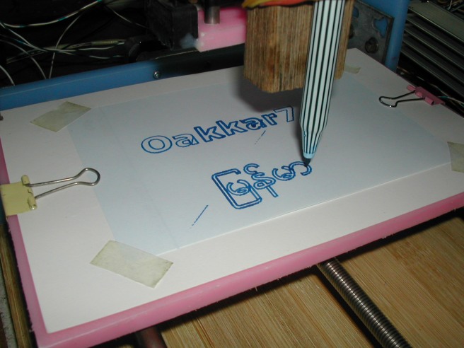
1# The first test was simple letter test. Draw some English and ျမန္မာ (this mean Myanmar ) in Inkscape. Save in “.dxf” format.

CNC_inkscape


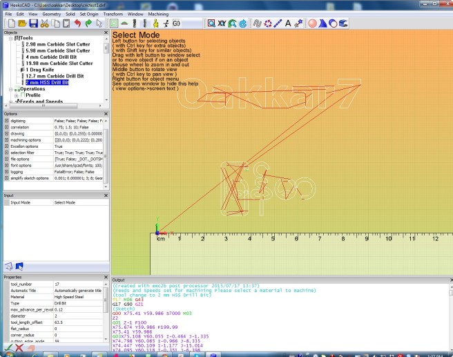
2# Convert “dxf” file  to G-code by HeeksCNC.

2015-07-17_133752

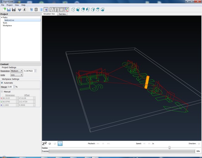
3# Simulated the G-code file and tool path with openSCAM.

2015-07-17_132658

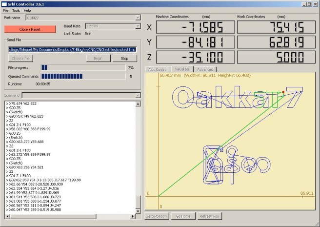
4# After simulation result is satisfied, then run actual job with Grbl Controller + csCNC.

2015-07-18_202733

Small one, csCNC is moving !!!

DIY_CNC_TestRun (7)


The first result is not bad at all.

Ready for next test.

DIY csCNC – 7 (Spindle, Autolevel and Milling Test)

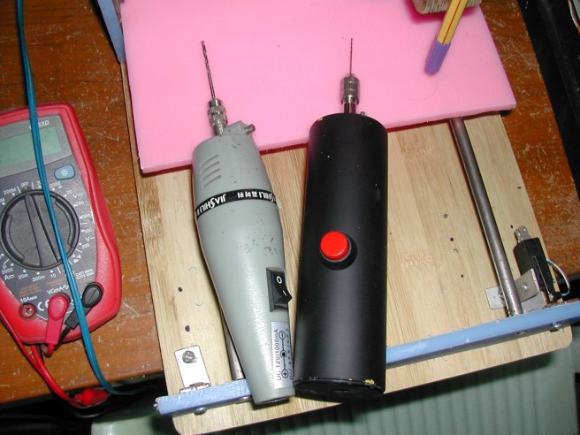
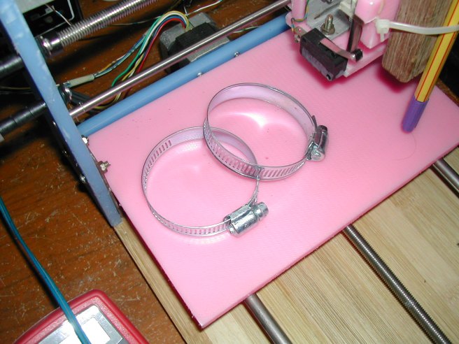
Spindle needs a lot of power and speed. But I have very limited resourced. First, I considered DIY style spindle but I cannot source right bearings and chuck or tool holder. So, I tried to use some small rotatory tools, PCB drill.

Some problems solved are:

  • CNC stopped with limit switch errors in a few minutes and after started milling. I checked limit switches and used a lot of methods such as filters, shield and cables but it didn’t work. I measured spindle motor’s power line (it is 12V DC ) and noticed some spikes. So, I replaced stocked 12V DC power supply with a good old quality power supply and the errors gone.
  • I know why everybody is talking about bed leveling. My first test did’t went well. I checked later that leveling error is about 2 mm from edge to edge of the bed 😦 .  Some said http://chilipeppr.com/tinyg but I preferred stand alone program and this worked fine.

https://github.com/martin2250/GrblHeightProbe2

  • The only problem is I used WinXP and the program required .net ver 4.5 and this version didn’t support WinXP. So, I forked and recompiled with .net version 3.5 and Visual Studio Express 2012 to support WinXP.

DSCN7751

DSCN7752

DSCN7753

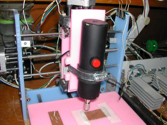
Unfortunately, they cannot do the jobs well. Seem RPM is low and tool holders is vibrated a bit.  So, I tried small rotatory tool and it does the job for the first time.

DSCN7755

DSCN7756

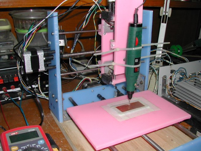
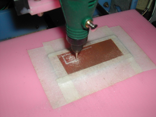
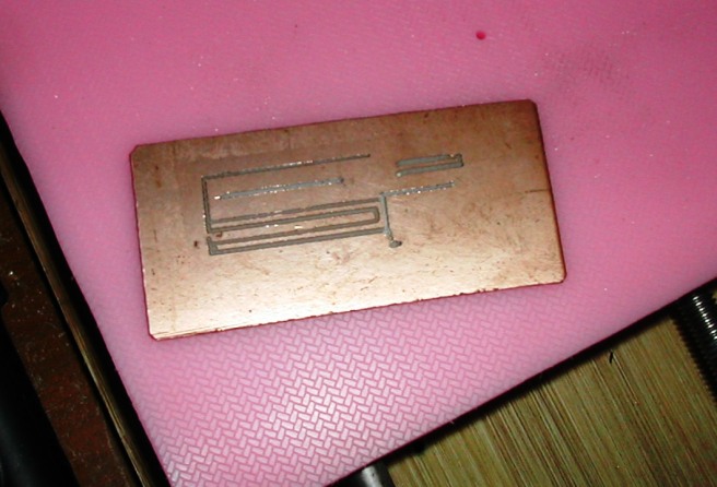
I did some tests for 1 mil , 2 mils and 4 mils PCB tracks. The result is not so bad for the first run.

DSCN7760

I don’t have proper CNC bits and waiting for the ordered bits for now. I will write a post about some final touch and tips and also about PC software soon.

DIY csCNC – 6 (Test running some jobs)

When Arduino meets PIC, csCNC was born. Before milling, I tested some jobs, text, drawing and also a sketch. See the video of csCNC drawing a sketch.

This is my DIY CNC machine which built for hobby and personal tool need. The designe is inspired by many CNC machines arround the net and used opensource Arduino based CNC controller name “grbl” and PIC based motor controller named “Linistepper”.   I use GRBL Controller 3.0 for PC software  and it worked well for the first run without tweaking too much.

After connecting everything, it is time to test some jobs.

  • Do you know who? 🙂
  • Ready to run

DIY_CNC_TestRun (2)

  • some test  run for text and Myanmar font

DIY_CNC_TestRun (1)

aung_san_suu_kyi_by_k_hots-d4hbrq1

  • Drawn by CNC

dassk_cnc

Results are not bad for first movement test. Next step is milling test.

Oakkar7


DIY csCNC – 5 (Connecting all, Grbl, Linistepper & Limit switches)

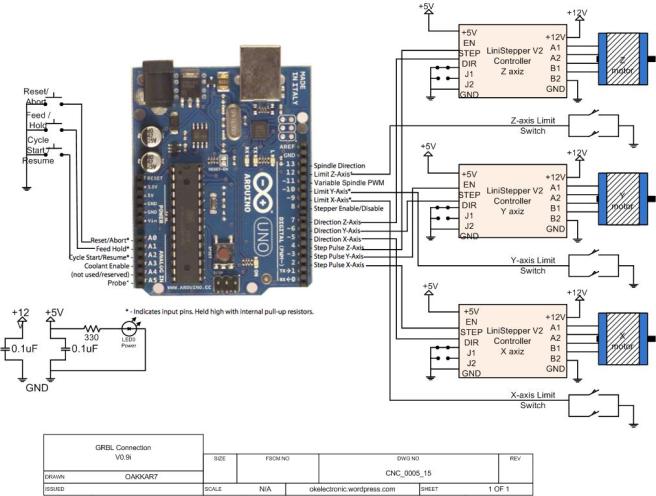
After pre-configuring grbl, time to assemble everything for the first test run. Here is my connection diagram for csCNC. Ref : grbl/wiki

https://github.com/grbl/grbl/wiki/Connecting-Grbl

My GRBL CNC Connection

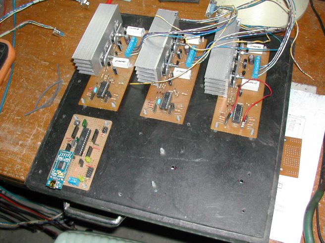
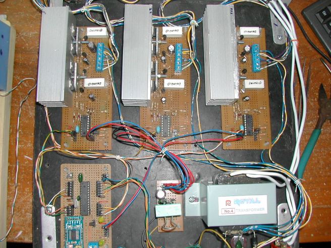
1# assembled everything on board,

DIY_CNC_grbl_linisteppers (1)

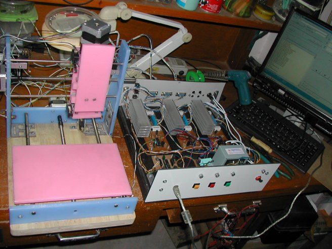
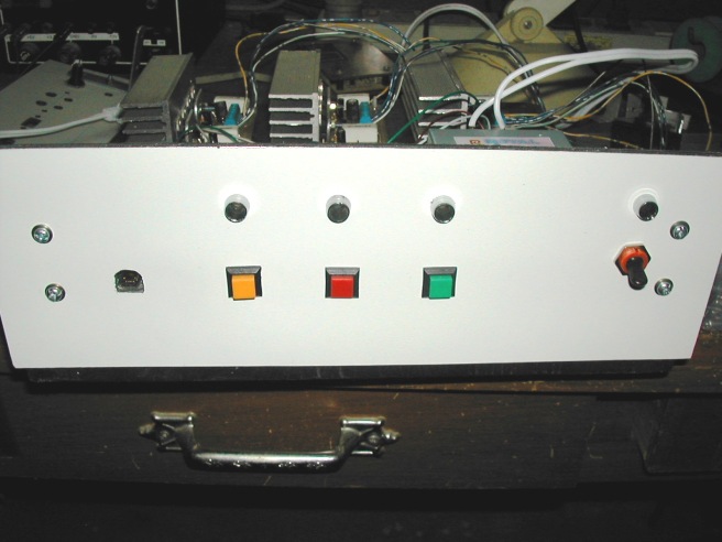
2# Added face plates and Grbl reset, Feed/Hold, Cycle/Resume, Power switch, LEDs, USB port and also a back plate with DB-9 connectors for steppers, 12V terminal for spinner, fuse house, limit switches female jacks

DIY_CNC_grbl_linisteppers (3)


3# Installed simple 12V/3A power supply with 220V/12V transformer and 7805 regulator for 5V supply.

DIY_CNC_grbl_linisteppers (4)

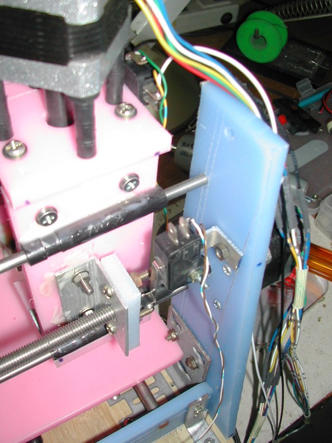
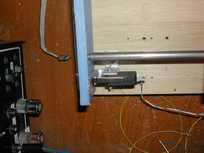
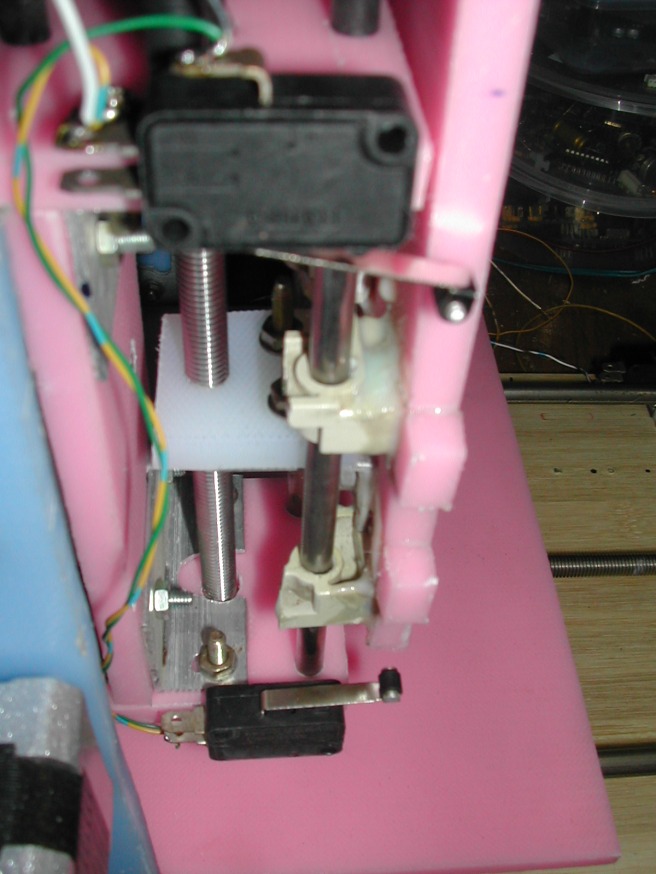
4# installed limit switches, wiring everything.

DIY_CNC_LimitSwitches (6)
X axis Limit Switch
DIY_CNC_LimitSwitches (4)
Y axis Limit Switch
DIY_CNC_LimitSwitches (2)
Z axis Limit Switches

Done! ready for test jogs.

DIY_CNC_TestRun (2)
DIY cs CNC and Grbl + Linistepper Controllers

AT Command Tester Tool

This is hayes AT command test too for SIMCOM GSM/GPRS modules (tested with SIM90X, SIM300 and SIM800 believed also work).  This is very early alpha test release and use at your own risk.
I am not a programmer but I am an engineer who wrote codes for need.
Developed by Visual Studio Express 2010 and .NET 4.0 (For winXP compatibility)
Last year, I developped a GSM base project with SIM908 module. Mostly, GSM and GPRS modules works with Hayes AT commands. (https://en.wikipedia.org/wiki/Hayes_command_set) This type of module can be interfaced by UART and can controlled functions such as call, SMS and others many. Any UART terminal like Putty, Hyper Terminal can be used for this but typing many commands re is a boring tasks in development. So, I developed this application with my own need and share with you now.
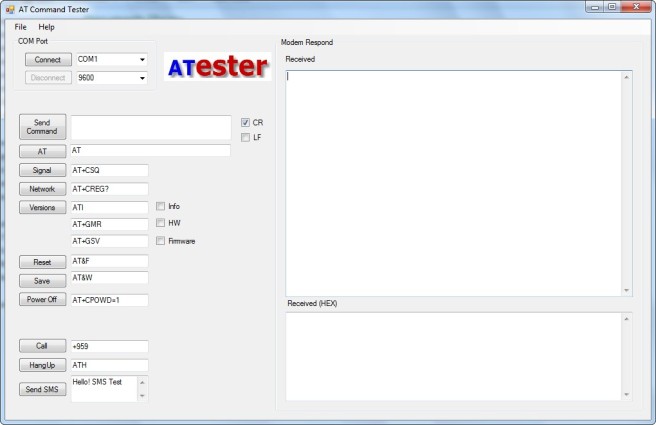
AT Tester main screen
Sample Connection diagram

Support the following AT commands.

  • AT AT command test
  • AT+CSQ GSM Signal strength
  • AT+CREG? Network Info
  • ATI Modem/Module informations
  • AT+GMR Hardware version
  • AT+GSV Firmware version
  • AT&F Modem reset
  • AT&W Configuration Save
  • AT+CPOWD=1 Power Off
  • ATD Voice Call
  • ATH HangUp Call
  • AT+CMGS SMS Sending
  • Also sending custom AT commands
  • receiving respond string from Modem and display in Hex format

How to run,

  1.  Connect PC and modules
  2.  Run ATester, choose COM port and speed, presses connect button.
  3.  Power up module. Will see “yyyyyyyyyy” like message when module is power up.
  4.  Press “AT” button, will see “OK” message in receive terminal is module is working.
  5.  Press “Signal” and “Network” buttons to check whether modem is associated with GSM network. Will show “+CSQ:22,0” for signal where 22 is signal quality (something liked bars in your handset). Higher number is indicated that strong in signal. For network, will show “+CREG: 1,1” “OK”. This means modem is associated with GSM network. Good to go.

Tips : Message reply with “OK” means command is corrected executed (not means it is worked). Message responds with “Error” indicates that there is error in command. Check details in AT command manual like this.

If these steps are fine, modem and software are working well. If something is wrong, consult with these ,

To be add

SMS Receiving Manny commands neet to add such as AT+CREG, AT+CGMI, AT+CGMM, AT+CGSN, AT+CGMR, AT+CIMI, AT+CPBR Decoding respond from modem (Some feedback string need to phrase for more understandable) GPS? Only for SIMXX8 modules GPRS support? Custom AT commands set editing and saving in config files for different modules.

I will add more commands and functions soon. Still tune.

Download:

https://github.com/oakkar7/ATester

oakkar7
okelectronic.wordpress.com

#SaveMyanmar #saveBurma

Mostly, I posted tech articles in my blog. But for now, things are worse than ever. Relentless monsoon rains in Myanmar have triggered flash floods and landslides, destroying thousands of houses, farmland, bridges and roads – with fast-flowing waters hampering relief efforts.

In Myanmar, “46 people have died and more than 200,000 have been affected by the floods across the country”, an official at the Relief and Resettlement Department said.

Myanmar is a vast and poor country, where communications and infrastructure are already weak, prompting the United Nations to warn that a full picture of the scale of the disaster may not emerge for days.

Authorities have declared the four worst-hit areas in central and western Myanmar “national disaster-affected regions”.

So, I would like to request you and all around the world. Help us.

Here is my recommended payment gateway provider and charity for donation.

https://m.2c2p.com/charityfund

FAQ https://medium.com/@aungkyawmoe/q-a-for-donation-for-myanmar-flood-8570544787ce

Update Donor list  https://m.2c2p.com/CharityFund/Home/TransactionList?page=1

MMR_0352_Flood_Affected_Tsps_A4_150729pm_v4 saveMyanmar


Thanks all,

Oakkar7

okelectronic.wordpress.com

DIY csCNC Controller – 4 (Grbl Config)

I have some experience in Mach3 CNC software in past. I love this software and the simple setup of Mach3 liked CNC controller software. Actually, it combines half of CNC and stepper controller functions in PC software. Even and old PC can be the best choice for this option. But there is one drawback or limitation in this, LPT port. Most of these software use LPT port for interfacing with stepper and CNC. Most modern PC no longer used LPT. Actually, I have some old laptop and PC with LPT builtin. But  I like to search the net for better option.

Yes, there must be two important things for me, must be free, opensource and simple.

After reading many DIY CNC build logs, I choose Grbl controller with DIY arduino board. For stepper, I already built Linistepper controllers.

GitHub Logo

From Grbl Wiki,

“Grbl is a free, open source, high performance software for controlling the motion of machines that move, that make things, or that make things move, and will run on a straight Arduino. If the maker movement was an industry, Grbl would be the industry standard.”

Thanks Grbl buys for developing such simple/effective controller.

It is time to assemble main controller after finishing DIY Arduino and stepper controller boards a few weeks ago. There are some tasks.

  1. Flashing Arduino with grbl firmware
  2. Configuring Grbl for my CNC machine
  3. Connecting Grbl with stepper controllers and CNC

1# The first test is to flash DIY Arduino board with “Grbl”. It is straight forward. Wiki is your help. Another helpful source is “Shapeoko”, fully opensource and commercial CNC wiki.

https://github.com/grbl/grbl/wiki/

https://github.com/grbl/grbl/wiki/Flashing-Grbl-to-an-Arduino

http://www.shapeoko.com/wiki/index.php/Grbl

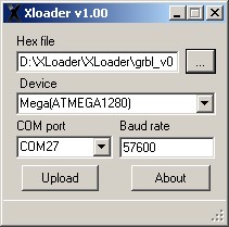
I used Xloader and flashing done after minutes. I used V0.9i version.

DIY_CNC_grbl (2)

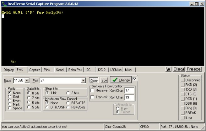
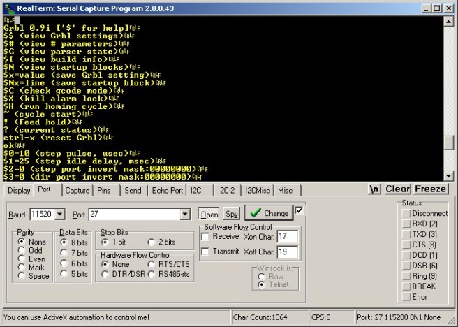
After flashing the Grbl firmware, I connected with 115200 baud rate and hit enter key. I saw Grbl version and some message. Grbl is alive.

DIY_CNC_grbl (3)

2# Configuring Grbl

I used last updated Grbl 0.9i version. This version is a bit different from old versions. Most of 0.9 user face difficulties in using this. And version 9.0x also has some issues with PC side software in some case. But, I choose this version 0.9i for testing some advanced features.

  • Default serial baudrate is now 115200! (Up from 9600)
  • Full Limit and Control Pin Configurability
  • Soft Limits
  • Probins
  • Compile-able via Arduino IDE!

2.1# Type “$” for help and “$$” for default configuration.

DIY_CNC_grbl (1)

Here is grbl default config. Before starting, check a look grbl wiki for how thing are sorted.

$0=10 (step pulse, usec)
$1=25 (step idle delay, msec)
$2=0 (step port invert mask:00000000)
$3=6 (dir port invert mask:00000110)
$4=0 (step enable invert, bool)
$5=0 (limit pins invert, bool)
$6=0 (probe pin invert, bool)
$10=3 (status report mask:00000011)
$11=0.020 (junction deviation, mm)
$12=0.002 (arc tolerance, mm)
$13=0 (report inches, bool)
$20=0 (soft limits, bool)
$21=0 (hard limits, bool)
$22=0 (homing cycle, bool)
$23=1 (homing dir invert mask:00000001)
$24=50.000 (homing feed, mm/min)
$25=635.000 (homing seek, mm/min)
$26=250 (homing debounce, msec)
$27=1.000 (homing pull-off, mm)
$100=314.961 (x, step/mm)
$101=314.961 (y, step/mm)
$102=314.961 (z, step/mm)
$110=635.000 (x max rate, mm/min)
$111=635.000 (y max rate, mm/min)
$112=635.000 (z max rate, mm/min)
$120=50.000 (x accel, mm/sec^2)
$121=50.000 (y accel, mm/sec^2)
$122=50.000 (z accel, mm/sec^2)
$130=225.000 (x max travel, mm)
$131=125.000 (y max travel, mm)
$132=170.000 (z max travel, mm)

# Important, you need to noted these before configuring grbl.

  • Your stepper controller, step pulse duration. If not sure, use default value, 10 us and trial and error method. (My Linistepper min step pulse is 3 us, so 10 us is fine for me)
  • X,Y,Z stepper motors step/revolution (eg: 200 steps/rev for my stepper specs)
  • Microstepping, half step or full step configuration for stepper motor controller ( I choose 6th microstep for my linisteppers )
  • X,Y, Z Lead screw’s pitch, turn/mm
  • X,Y,Z axis maximum travel distance Not your bed or axis dimension, how much your axis actually moved. (Mine is X=160 mm , Y = 160 mm and Z = 55 mm)
  • Have  you use limit switches for homing and max limits of each axis? Some very small CNC machine may not use limit switches but strongly recommended to use in most case. It will convenience and protect crashing your machine. I used 2 x limit switches for each axis, total six, used for both max limit and homing.

# Some parameters should be configured after you connect grbl with steppers controllers and CNC. For example, axis direction should be configure after the first test run. After you test move one axis, if you check and want to reverse, simple configure this option at that time. I also noted these configs as post configurations.

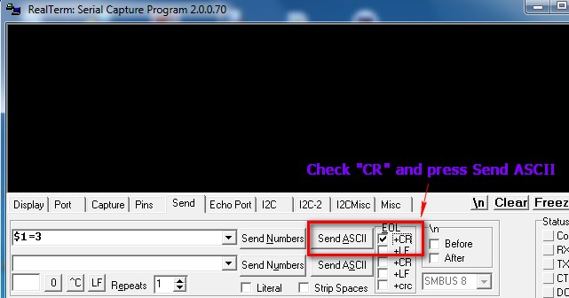
2.2# OK, configuring parameters is simple. You can use any serial Terminal software like putty. I use RealTerm, my fav serial Terminal software. Type the parameter and value exactly, press Enter and grbl will save the new value in EEPROM instantly.

For example, to configure new step pulse value 3 us, just type in and press Enter this.

$1=3

Sample screen shoot from RealTerm.
grbl_config3
Just sample screen shoot for putty. Type in at the terminal window.
grbl_config2

2.3# Axis Direction ($3)

#(This should be a post configuration after finishing connection with CNC hardware)

There are many explanations in many forums. I want is simple. Just drive test my X, Y, Z motor after finish all config. I checked my Z axis direction is wrong Up and Down. I just set the Z-axis dir invert bit as “1”. You need to set only 3 bits, LSB is for X axis. Second LSB bit is for Y. Third LSB bit for Z. In my case, I want to invert Z direction only and mask in binary is “00000100” and “4” in decimal. So, the config is like this.

$3=4

2.4# Homing Config

Arr, homing in grbl is a bit confusing thing. I notice many people troubled in this.

OK, first thing first. I used limit switches and homing. So, pre-configure these two first.

$21=1
$22=1

#This is also a post config.  Then check your homing direction by entering “$H” command after you finished connection with CNC machine. Like axis dir inverse mask, if your homing direction of XYZ axis is wrong, just SET inverse mask bit. That all. I checked later that my X,Y axis homing directions are wrong. So, I set the bits for XY and my mask is “00000011” and in decimal, it is “3”.

$23=3

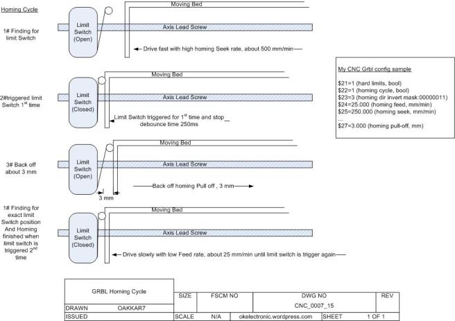
# Again, it should be also post config.  Homing feed rate and seek rate. It is the most confusing part in Grbl. Grbl homing cycle always take two steps, seeking and feeding. First, it drives the axis with faster seek rate (in default $25=635.000 (homing seek, mm/min, mine is 250 mm/min). So, the axis drive to limit switch very fast in first seek cycle. Be aware, if seeking rate is too him your stepper will not move and stalled, start with 250 and increase until the highest speed.  When the axis hit limit switch, it back-off a few mm until release the switch (in default 1 mm, $27=1.000 (homing pull-off, mm), mine is 3 mm). After the switch is released, the axis drive forward again with slower rate to determine the exact position of limit switch trigger ($24=50.000 (homing feed, mm/min), in most case, default is fine). After limit switch is triggered again, homing for this axis is finished.

Here is my homing seek,feed and pull-off configs. Also see the fig for homing cycle.

$24=25.000
$25=250.000
...
$27=3.000

2.5# 2.5# Axis Step per Milimeter
This is configured how many steps needs for axis driver to drive 1 mm distance. There is a formula in grbl wiki.

steps_per_mm = (steps_per_revolution*microsteps)/mm_per_rev

Here is my driver config,

Step/Rev =200

Microstep = 6

mm/rev = 1.2876

Then, Step/mm = (200×6)/1.2876 = 931.966  ( 3 digits and 3 decimal place format)

Then, configured for grbl

$100=931.966
$101=931.966
$102=931.966

2.6# Last, Max travel distance for ZYZ Axis

Just need to configure the max movable distance for all axis. Need to measure your axis movement carefully. My config is as follows.

$130=160.000
$131=160.000
$132=55.000

Finally, here is my Grbl config. I used limit switches and homing. The rest are left in default.

$0=10 (step pulse, usec)
...
$3=4 (dir port invert mask:00000100)
...
...
$21=1 (hard limits, bool)
$22=1 (homing cycle, bool)
$23=3 (homing dir invert mask:00000011)
$24=25.000 (homing feed, mm/min)
$25=250.000 (homing seek, mm/min)
...
$27=3.000 (homing pull-off, mm)
$100=931.966 (x, step/mm)
$101=931.966 (y, step/mm)
$102=931.966 (z, step/mm)
$110=300.000 (x max rate, mm/min)
$111=300.000 (y max rate, mm/min)
$112=300.000 (z max rate, mm/min)
...
$130=160.000 (x max travel, mm)
$131=160.000 (y max travel, mm)
$132=55.000 (z max travel, mm)

Next part is assembling and connecting all together.
Oakkar7
okelectronic.wordpress.com

DIY csCNC Controller – 3 (DIY Arduino Board and Programming with BusPirate)

For CNC controller, we have two choices, PC or dedicated controller card. Most DIY designs use Mach-3 or LinuxCNC. They use LPT port for interfacing and PC side software take care of everything. The problem is that LPT port is not an option today PC even for a bit outdated one. I searched for opensource CNC controller with simple, cheap, DIY friendly building solution 🙂 . Most are not meet up for me.

Finally, I keep my eye on Grbl.

https://github.com/grbl/grbl

https://github.com/grbl/grbl/wiki

– It is opensource, Arduino base, quoted from Grbl wiki

“Makers who do milling and need a nice, simple controller for their system that will run the ubiquitous Arduino Uno. People who loathe to clutter their space with legacy PC-towers just for the parallel-port. Tinkerers who need a controller written in tidy, modular C as a basis for their project.”

I am a PIC guy but the simplicity and rich full featured lib and software support of Arduino swayed my mind. Every programming language and platform has it’s learning curve but Arduino is not. If you have experience on any microcontroller paltform, you can build it up Arduino within a few hours.

In short, I built my own Arduino board (based on UNO core). I don’t want to scarified my  Arduino board in CNC project and want to save a few bucks and also wanna to have fun.

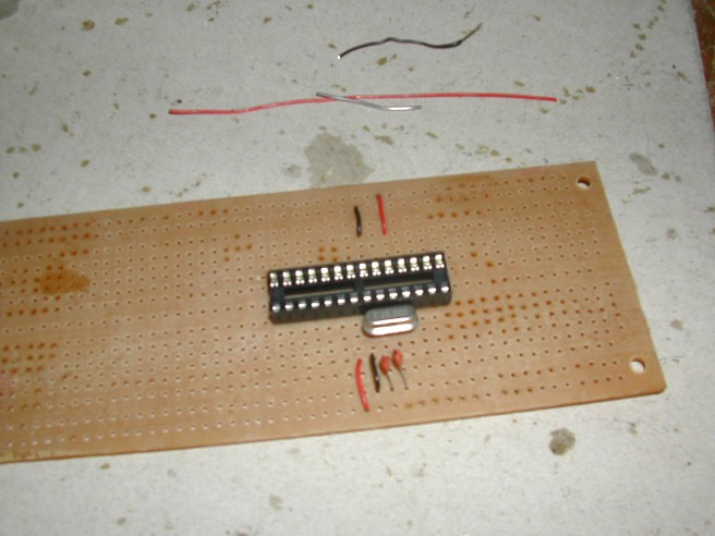
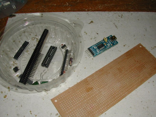
1# Started using a perfboard, a ATMEGA328P, crystal, some capacitor and resistor, headers, pin base and some jumper wires and also FTDI FT232 board.

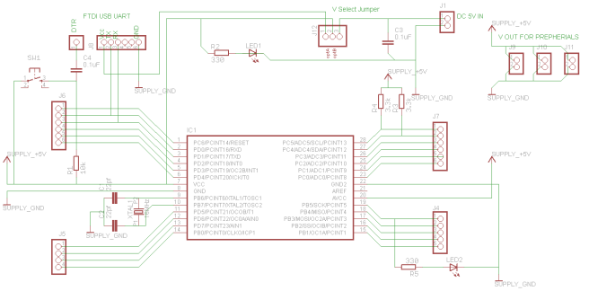
Started with basic design, I omitted power supply parts. Here is my basic sketch schematic.

MY_DIY_Arduino-Circuit

DIY-Arduino-Hardware (1) DIY-Arduino-Hardware (2)

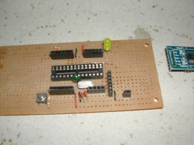
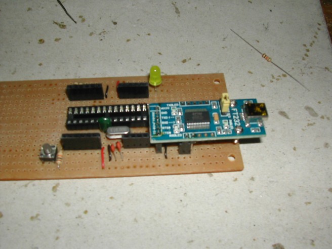
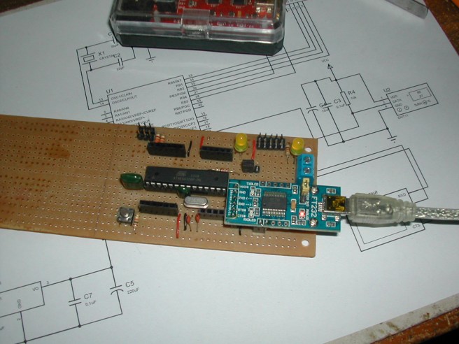
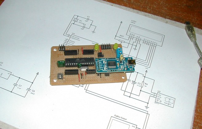
2# Soldered headers, LED at PIN-13 and Reset switch. Also a header for FTDI board, external power connector, jumper for USB power, Power LED, pulled up resistors for SDA and SCL are soldered. Dont forget FTDI-DTR pin to connect RESET pin of ATMEGA328. If not, you cannot program Arduino.

DIY-Arduino-Hardware (5)

DIY-Arduino-Hardware (6)

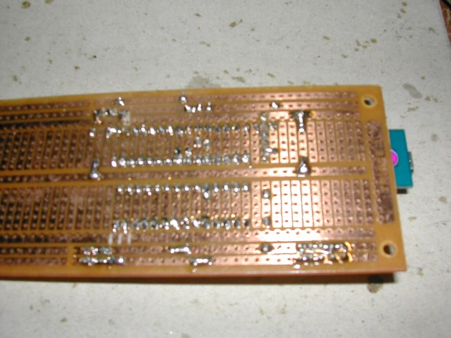
3# The back side or perfboard PCB.

DIY-Arduino-Hardware (7)

After building the board, I have to program the ATMEGA328 with bootloader. The procedure is simple but I need a programmer for this. There are some alternative methods for burning bootloader to Arduino.

– http://www.arduino.cc/en/Tutorial/ArduinoToBreadboard

– https://learn.adafruit.com/arduino-tips-tricks-and-techniques/arduinoisp

– https://learn.sparkfun.com/tutorials/installing-an-arduino-bootloader

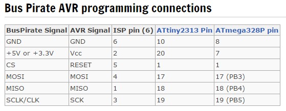
I picked my buspirate and follow the procedure from this blog. Thanks, BP support as AVR programmer.

http://blog.allthingsgeek.com/article/index/index/id/27

http://dangerousprototypes.com/docs/Bus_Pirate_AVR_Programming

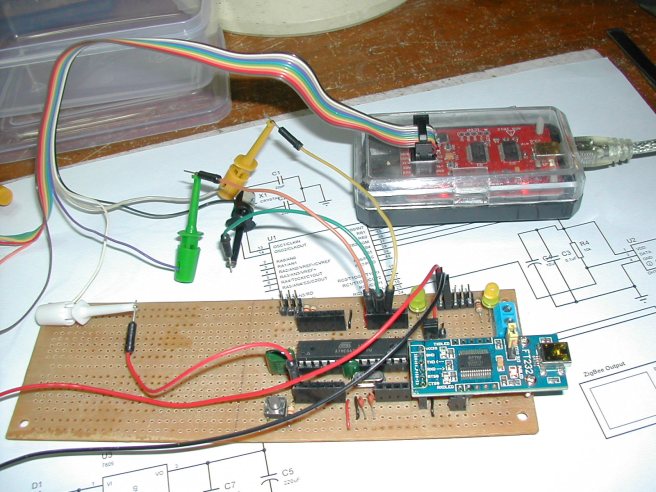
1# Connected the Arduino board and Buspirate .

buspirate-AVR_Programmer

DIY-Arduino-Buspirate

2# Download “optiboot-master” from Arduino source.  Installed WinAVR for AVRdude programmer support for Windows.

https://github.com/Optiboot/optiboot

http://winavr.sourceforge.net/download.html

According to Eric’s blog post, I created a .bat file for easy programming.

PAUSE
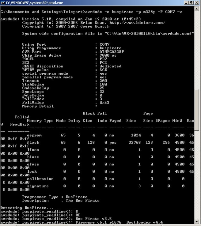
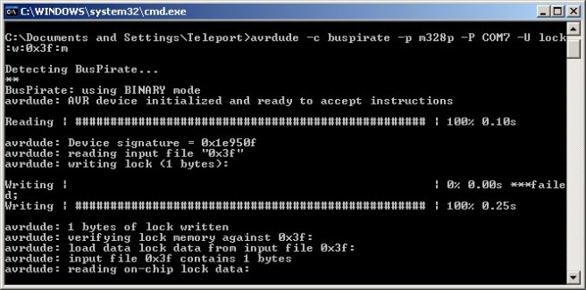
avrdude -c buspirate -p m328p -P COM7 -U lock:w:0x3f:m
avrdude -c buspirate -p m328p -P COM7 -U efuse:w:0x05:m -U hfuse:w:0xD2:m -U lfuse:w:0xFF:m -U flash:w:optiboot_atmega328.hex -U lock:w:0x0F:m
PAUSE

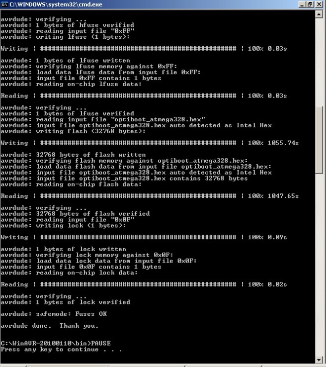
3# Then, simply run in command line, waited for 10 mins (yes, it is a bit slow) and the job was done.

DIY-Arduino-Firmware (8) DIY-Arduino-Firmware (9)

DIY-Arduino-Firmware (1)

4# Plug USB cable, just build a “blink” sketch and successfully upload and run. LED at PIN-13 is blinking successfully 😀 .

DIY-Arduino-Hardware (15)

Finished DIY Arduino board.

DIY-Arduino-Hardware (16)

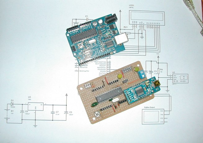
5# Side by side with original Arduino.

DIY-Arduino-Hardware (17)

Last job is need to attach all and make the first run.

By Oakkar7
okelectronic.wordpress.com

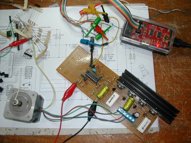
DIY csCNC – 2 (Linistepper Driver and testing with Buspirate)

Since I started building DIY CNC, I checked the free, opensource motor controller. There are several alternatives. I chose linisteppr controller.

http://www.piclist.com/techref/io/stepper/linistep/index.htm

http://www.romanblack.com/lini.htm

  • – Simple and cheap (my first priority 🙂 ) and I can source required parts locally
  • –  microstepping, open design (Especially, it’s PIC16F628A based. I’m PIC guy and a lot 16F628A in my stock)

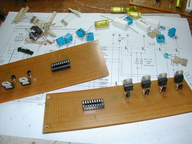
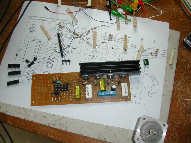
Build log is fast, simple and straight. I used a simple perfboard for faster development.

DIY-linistepper (1) DIY-linistepper (2)


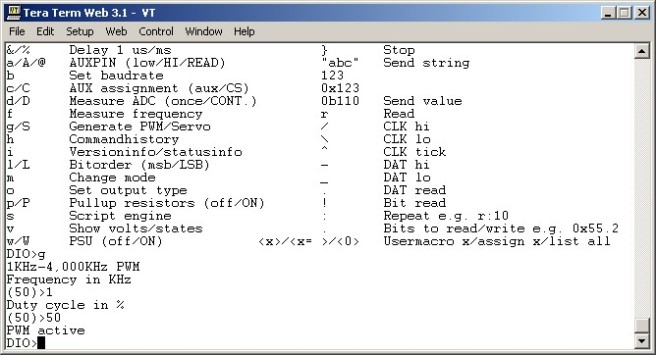
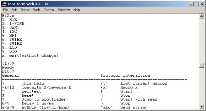
After building the driver, I tested it with my buspirate using PWM function for generating stepping pulse. I started with 1kHz and increased to 4 kHz.

  • – Buspitrate GND and AUX pin were connected to driver STEP and GND pins
  • – For full step, motor was stalled at 1 kHz
  • – The motor is smoothly run at 1 kHz at half step and 6th microstepping
  • – The motor running faster and smoother at 4kHz for 16th microstepping
  • Need bigger heatsink or small fan, sa mention in linistepper page,it is hot a lot

linistepper-buspirate (2) linistepper-buspirate (3)

DIY-linistepper (4)

The next part is the CNC controller and software.

By Oakkar7
okelectronic.wordpress.com